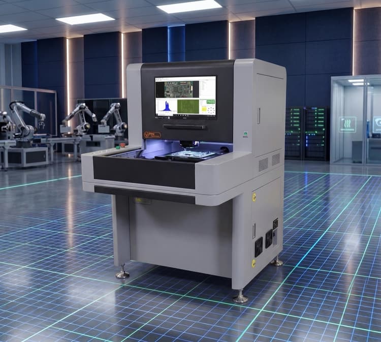
LineMaster DMI
A revolutionary dual-mode offline platform that merges ASC International's 3D SPI sensor technology with image and algorithm-based AOI in a single system.
The LineMaster DMI inspects both the solder paste printing process and component placement in one pass — detecting missing parts, incorrect components, bridging, polarity issues, tombstoning, and more. With lateral resolution down to 10–15μm, the DMI handles 01005 components and the most demanding miniaturization requirements.
LineMaster DMI specifications
A dual-mode system that runs 3D solder paste inspection and AOI in one machine, so one station checks both the print and the placement. Boards up to 455 mm x 355 mm as standard, 660 mm x 558 mm as an option.
SPI Sensor
| Measurement Principle | Phase Shift Interferometry |
|---|---|
| Camera Type | High Resolution Color CCD |
| Z Resolution | 0.48 µm (0.019 mils) |
| Illumination | LED Based White Light |
AOI Sensor
| Camera Type | High Resolution Color CCD |
|---|---|
| Analysis Method | Image and Algorithm Based |
| Illumination | LED Based Multi Color Light |
General Specification
| Max Board Size | 455 mm x 355 mm (18” x 14”) |
|---|---|
| Max Board Size, Optional | 660 mm x 558 mm (26” x 22”) |
| Safety Feature | Light Curtain Guard |
| Power | 100-240 VAC, 50-60 Hz, 2 Amps |
What it measures
- SPI: True Height, Area, Volume, X-Y, Registration and Bridging
- AOI: Absence/Presence, Polarity, OCV, Solder with Bridging, etc.
Options
- Offline Programming and Rework Station
- Max Board Size 660mm x 558 mm (26” x 22”)
Source: LineMaster Fusion Dual Mode 3D SPI/AOI datasheet. Specifications can change; confirm current figures with ASC when you request a quote.
Common questions about the LineMaster DMI
How is AOI programmed?
From component placement library or CAD data (CPL). SPI programs come from a Gerber import, which the sheet says takes less than 5 minutes.
What board size does it take?
455 mm x 355 mm (18” x 14”) standard, with an optional 660 mm x 558 mm (26” x 22”).
What SPC data does it produce?
X and Moving Range, X-Bar and Sigma, X-Bar and Range, and Histogram with Cp and Cpk for SPI. Reports export in .csv format.
Full Specifications
The datasheet covers dimensions, camera and vision system specs, and full defect detection capabilities.